10.5 cm fortress guns–world history and facts
10.5 cm fortress guns
A special weapon worth mentioning here is the 10.5 cm turret cannon , which will be dealt with in a separate article.
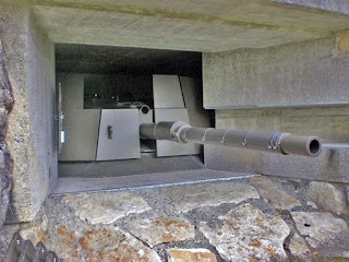
The remaining guns listed are fortress guns for a minimal embrasure opening ( minimum embrasure ). This means that the opening in the notch is just big enough for the gun barrel to fit through.
These 10.5 cm guns and howitzers were mostly installed in rock works. In areas where there were no rocks, open pit bunkers were also built. The positions in Faulensee and Jaunpass are striking examples .
Not all fortresses were initially equipped with the above guns. Some of the fortresses were reinforced with field artillery pieces.
This was primarily due to the lack of special bunker weapons or the 12 cm field howitzers, which were already older at the time in the mid-1940s , were installed.
Systems that were planned to be armored with field artillery can usually still be recognized today by the rather wide tunnels that were necessary so that the guns on the field carriages could be driven into the gun turrets.
All field guns were replaced by permanently installed guns on lever or column mounts by the end of the Second World War.
10.5 cm L42 gun on a stand mount
The procurement of the 10.5 cm gun was decided in 1934. The first guns were delivered by the Swedish company Bofors. The guns were then manufactured under license by K+W in Thun.
The Bofors gun had a perforated muzzle brake, which the K+W Thun replaced with a dual-chamber muzzle brake. The designation of the gun is: 10.5 cm Fest Kan 39 L42.
stand carriage
With the stand mount, most of the pipe is in the bunker. Only the front part protrudes from the notch opening to the outside. This has the advantage that the gun barrel is well protected from external influences. A disadvantage of this system is that the breech can hardly be reached at low elevations without aids for the loader.
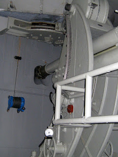
The carriage consists of a base plate and stand. The stand is guided on the circular links of the base plate. The centers of the circular guide carriages of the base plate and stand are arranged in such a way that the imaginary pivot point of the tube lies in the outlet opening of the armor plate.
At the upper end, the stand is guided by a drawbar by means of a trolley in the circular segment of the formwork. To reduce friction, the stand rolls on adjustable spring-loaded ball bearings on the baseplate cheeks.
Source: Wikipedia




.jpg)

.jpeg)


.jpeg)

Comments
Post a Comment